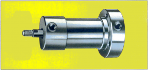
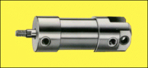
Slide thumbnail

Cilindros serie AL

CARACTERÍSTICAS

Nociones generales

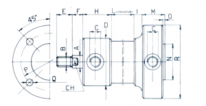
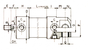
Esta serie comprende diámetros

pequeños medianos:

Diámetro

Salidas

20

1/8’’ gas

27

1/8’’ gas

35

1/8’’ gas

40

1/8’’ gas

50

1/8’’ gas

58

1/4’’ gas

70

1/4’’ gas

85

1/4’’ gas

100

1/4’’ gas

Número de efectos

Los cilindros de esta serie se construyen en la versión de doble efecto (utilizable también en la versión de simple efecto sin muelle de retorno) y en la versión de simple efecto con muelle de retorno.

Fabricación sobre pedido

Es posible el suministro de cilindros con rascador del vástago. Cilindros con amortiguador anterior y/o posterior regulables.

Construcción

TIPO DE MONTAJE
Sujeción con patas (P)
Brida anterior (FA)
Brida posterior (FP)
Rosca anterior (V)
Charnela (C)
Brida Ant. reducida (RFA)
Brida Pos. reducida (RFP)
Charnela reducida (RC)
Diámetro interior (mm)   Recor.    Base Fuerza a
6 kg/cm²
Fuerza máx.
12 kg/cm²
Cap. (Lt.)
20 20 18 37 0,0063
27 25 34 68 0,0143
35 35 57 114 0,0336
40 60 75 150 0,075
50 70 118 236 0,137
58 60 158 316 0,158
70 70 231 462 0,268
85 90 340 680 0,510
100 100 471 942 0,785

Características técnicas

Diámetro mm. 20 27 35 40 50 58 70 85 100
Recorrido min. mm. 2
Tolerancias   ± 0,5 mm. con recorridos hasta 100 mm.
± 1 con recorridos superiores a 100 mm.
Temperatura ambiente mín.
máx.
ºC – 20º
ºC + 90º
Presión de ejercicio Kp/cm² 12
Presión   simple efecto
Mínima  doble efecto
Kp/cm²
Kp/cm²
0,5 ¸ 1,5
0,3 ¸ 0,8
Entradas Gas 1/8’’ 1/8’’ 1/8’’ 1/8’’ 1/4’’ 1/4’’ 1/4’’ 1/4’’ 1/4’’
Diámetro vástago mm. 8 10 12 12 14 16 18 20 24

DESPIECE

1  Acero Inox o Cromo Duro 5  Nylón 9  Nylón
2  Latón, Acero, Alumnio o Inox 6  Goma anti-aceite  
3  Alumnio o Acero 7  Aluminio o Acero  
4  Acero o Acero Inox 8  Goma anti-aceite  

MODELOS DE CILINDROS

Diámetro Carrera
base
A B C CH D F G L N O P Q R S T U V Z
* ** * **
20 20 8 M 6 x 1 1/8’’ 6 31 9 8 44 2 2 17 8 21 4,25 42 32 10 10 8 19 13
27 25 10 M 8 x 1,25 1/8’’ 8 37 12 10 48 4 10 19,5 10 25 4,5 45 55 20 30 8 20 17
35 35 12 M10 x 1,5 1/8’’ 10 45 15 12 52 5 11 22,5 12 25 5,5 64 78 20 26 8 20 17
40 60 12 M10 x 1,5 1/8’’ 10 50 15 12 64 4 10 25 14 30 5,5 64 78 20 26 8 25 22
50 70 14 M12 x 1,75 1/8’’ 12 61 18 14 64 6 12 30,5 16 32 5,5 77 93 26 32 10 22 22
58 60 16 M14 x 2 1/4’’ 14 70 21 16 66 7 18 35 16 35 6,5 86 102 27 38 10 26 25
70 70 18 M16 x 2 1/4’’ 16 82 24 18 71 8 19 41 18 36 6,5 100 118 28 39 10 28 26
85 90 20 M18 x 2,5 1/4’’ 18 98 27 20 83 8 20 49 20 38 8,5 118 138 30 42 11 27 27
100 100 24 M20 x 2,5 1/4’’ 20 114 30 24 90 9 21 57 22 40 8,5 136 158 33 45 12 28 28

Diámetro Recorrido
base
A B C CH D F G H I L M N O P Q R
* **
20 20 8 M 6 x 1 1/8’’ 6 30 9 8 6 38 11 2 2 3,5 23 2 50 4,25 39
27 25 10 M 8 x 1,25 1/8’’ 8 35 12 10 7 41 13 4 10 4 30 2 48 4,5 58
35 35 12 M10 x 1,5 1/8’’ 10 45 15 12 8 44 14 5 11 4 36 2 54 5,5 66
40 60 12 M10 x 1,5 1/8’’ 10 50 15 12 10 54 15 4 10 3 40 3 57 6,5 69
50 70 14 M12 x 1,75 1/8’’ 12 61 18 14 10 54 18 6 12 3 54 3 75 6,5 87
58 60 16 M14 x 2 1/4’’ 14 70 21 16 11 55 18 7 18 4 60 3 82 6,5 100
70 70 18 M16 x 2 1/4’’ 16 82 24 18 14 57 19 8 19 4 701 4 10 8,5 119
85 90 20 M18 x 2,5 1/4’’ 18 98 27 20 15 68 21 8 20 4 80 4 120 10,5 140
100 100 24 M20 x 2,5 1/4’’ 20 114 30 24 16 74 23 9 21 4 88 4 137 10,5 160

Diámetro Carrera
base
A B C CH D F G H I L M N O P Q R
* **
20 20 8 M 6 x 1 1/8’’ 6 30 9 8 16 28 6 2 2 20 23 2 39 4,2 50
27 25 10 M 8 x 1,25 1/8’’ 8 35 12 10 20 28 8 4 10 21 30 2 48 4,5 58
35 35 12 M10 x 1,5 1/8’’ 10 45 15 12 24 28 9 5 11 21 38 2 59 5,5 69
40 60 12 M10 x 1,5 1/8’’ 10 50 15 12 32 32 8 4 10 24 40 3 62 5,5 74
50 70 14 M12 x 1,75 1/8’’ 12 61 18 14 32 32 8 6 12 24 50 3 75 6,5 87
58 60 16 M14 x 2 1/4’’ 14 70 21 16 32 34 9 7 18 27 62 3 86 8,5 100
70 70 18 M16 x 2 1/4’’ 16 82 24 18 35 36 12 8 19 26 72 4 100 8,5 119
85 90 20 M18 x 2,5 1/4’’ 18 98 27 20 44,5 38,5 11 8 20 29 80 4 120 10,5 140
100 100 24 M20 x 2,5 1/4’’ 20 114 30 24 50 40 13 9 21 32 88 4 137 10,5 160

Diámetro Carrera
base
A B C CH CH1 D E F G H I L M N O
* **
20 20 8 M 6 x 1 1/8’’ 32 6 30 9 8 16 28 11 2 2 3,5 5 M24x2
27 25 10 M 8 x 1,25 1/8’’ 35 8 35 12 10 20 28 13 4 10 4 6 M28x2
35 35 12 M10 x 1,5 1/8’’ 40 10 45 15 12 24 28 14 5 11 4 7 M32x2
40 60 12 M10 x 1,5 1/8’’ 45 10 50 15 12 32 32 15 4 10 3 8 M36x3
50 70 14 M12 x 1,75 1/8’’ 50 12 61 18 14 32 32 18 6 12 3 10 M42x3
58 60 16 M14 x 2 1/4’’ 55 14 70 21 16 32 34 18 7 18 4 10 M45x3
70 70 18 M16 x 2 1/4’’ 60 16 82 24 18 35 36 19 8 19 4 10 M50x3
85 90 20 M18 x 2,5 1/4’’ 70 18 98 27 20 44,5 38,5 21 8 20 4 12 M60x4
100 100 24 M20 x 2,5 1/4’’ 85 20 114 30 24 50 40 23 9 21 4 14 M70x4

Diámetro Carrera
base
A B C CH D F G H I L M N O P Q R
* **
20 20 8 M 6 x 1 1/8’’ 6 30 9 8 16 28 11 2 2 10 6 8 22 5 24
27 25 10 M 8 x 1,25 1/8’’ 8 35 12 10 20 28 13 4 10 21 7 9 25 6 28
35 35 12 M10 x 1,5 1/8’’ 10 45 15 12 24 28 14 5 11 23 9 12 32 8 32
40 60 12 M10 x 1,5 1/8’’ 10 50 15 12 32 32 15 4 10 26 10 18 40 10 36
50 70 14 M12 x 1,75 1/8’’ 12 61 18 14 32 32 18 6 12 18 12 25 49 12 42
58 60 16 M14 x 2 1/4’’ 14 70 21 16 32 34 18 7 18 33 14 26 54 14 45
70 70 18 M16 x 2 1/4’’ 16 82 24 18 35 36 19 8 19 35 16 35 67 16 50
85 90 20 M18 x 2,5 1/4’’ 18 98 27 20 44,5 38,5 21 8 20 36 18 40 76 18 60
100 100 24 M20 x 2,5 1/4’’ 20 114 30 24 50 40 23 9 21 45 20 40 80 20 70

Diámetro Carrera
base
A B C CH D F G H I L M O P Q R
* **
20 20 8 M 6 x 1 1/8’’ 6 30 9 8 19 9 12 2 2 3,5 2 39 4,25 50
27 25 10 M 8 x 1,25 1/8’’ 8 35 12 10 19 9 13 4 10 4 2 48 4,5 58
35 35 12 M10 x 1,5 1/8’’ 10 45 15 12 19 9 14 5 11 4 2 54 5,5 66
40 60 12 M10 x 1,5 1/8’’ 10 50 15 12 21 11 15 4 10 4 3 57 6,5 69
50 70 14 M12 x 1,75 1/8’’ 12 61 18 14 24 11 18 16 22 4 3 75 6,5 87
58 60 16 M14 x 2 1/4’’ 14 70 21 16 24 11 18 17 28 4 3 82 6,5 100
70 70 18 M16 x 2 1/4’’ 16 82 24 18 23 13 19 20 31 4 4 100 8,5 119
85 90 20 M18 x 2,5 1/4’’ 18 98 27 20 25 13 20 21 33 4 4 120 10,5 140
100 100 24 M20 x 2,5 1/4’’ 20 114 30 24 27 13 21 23 35 4 4 137 10,5 160

Diámetro Carrera
base
A B C CH D F H I L M N O P Q
* **
20 20 8 M 6 x 1 1/8’’ 6 30 9 8 28 11 2 2 10 6 8 22 5
27 25 10 M 8 x 1,25 1/8’’ 8 35 12 10 28 13 4 10 21 7 9 25 6
35 35 12 M10 x 1,5 1/8’’ 10 45 15 12 28 14 5 11 23 9 12 32 8
40 60 12 M10 x 1,5 1/8’’ 10 50 15 12 32 15 4 10 26 10 18 40 10
50 70 14 M12 x 1,75 1/8’’ 12 61 18 14 32 18 16 22 28 12 25 49 12
58 60 16 M14 x 2 1/4’’ 14 70 21 16 34 18 17 28 33 14 25 54 14
70 70 18 M16 x 2 1/4’’ 16 82 24 18 36 19 20 31 35 16 35 67 16
85 90 20 M18 x 2,5 1/4’’ 18 98 27 20 38,5 21 21 33 36 18 40 76 18
100 100 24 M20 x 2,5 1/4’’ 20 114 30 24 40 23 23 35 45 20 40 80 20


Este accesorio se compone de tres partes:

  1. La horquilla, construida en acero.
  2. El perno, de acero bruñido
  3. Los dos anillos elásticos de acero  especial.

Tipo A B B Tolerancias acoplamiento C D E E Tolerancias acoplamiento F G H N Q R
FPF6 M 6 x 1 6 H-11 10 12 6 H-13 12 24 31 18 12 19
FPF8 M 8 x 1,25 8 H-11 14 16 8 H-13 16 32 42 22 12 30
FPF10 M 10 x 1,5 10 H-11 18 20 10 H-13 20 40 52 27 15 37
FPF12 M 12 x 1,75 12 H-11 20 24 12 H-13 24 48 62 31 18 44
FPF14 M 14 x 2 14 H-11 24 27 14 H-13 27 56 72 34 23 49
FPF16 M 16 x 2 16 H-11 26 32 16 H-13 32 64 83 39 24 59
FPF18 M 18 x 2,5 16 H-11 26 32 16 H-13 32 64 83 39 24 59
FPF20 M 20 x 2,5 16 H-11 35 45 23 H-13 25 65 80 54 31 49
FPF24 M 24 x 3 20 H-11 50 60 30 H-13 30 85 105 69 42 63
FPF27 M 27 x 3 20 H-11 50 60 30 H-13 30 85 105 69 42 63
FPF33 M 33 x 3,5 30 H-11 55 70 30 H-13 35 87 120 80 40 80