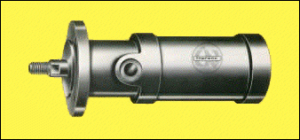
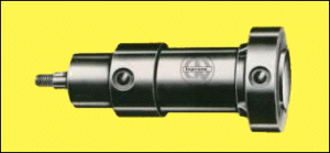
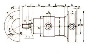
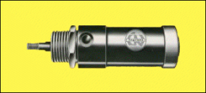
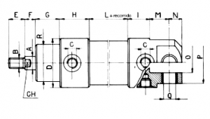
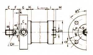
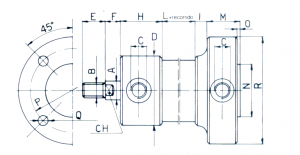
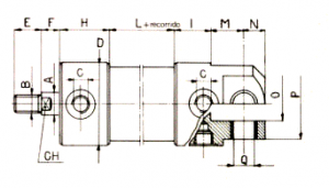
Slide thumbnail

Cilindros serie AL

CHARACTERISTIC

General features

This series include small
medium diameters:

Diameter

Exit Flow

20

1/8’’ gas

27

1/8’’ gas

35

1/8’’ gas

40

1/8’’ gas

50

1/8’’ gas

58

1/4’’ gas

70

1/4’’ gas

85

1/4’’ gas

100

1/4’’ gas

Acting Numbers

Built in doublé acting cylinder series can be used as a single Acting springs return or as a single acting spring return .

Manufacture order upon request

Cylinders avaibles with piston rod scraper
Cylinders with adjustable front and back cushions

Construction

MANUFACTURING AND ASSEMBLY
Fixing points with fout(P)
Previous Bridle(FA)
Later Bridle(FP)
Previous Crossed(V)
Hinge(C)
Limited Hinge(RC)
Previous limited bridle(RFA)
Later limited bridle(RFP)
Inside diameter (mm) Base force Force 6 kg/cm² Force maxim.
12 kg/cm²
Capacity (Lt.)
20 20 18 37 0,0063
27 25 34 68 0,0143
35 35 57 114 0,0336
40 60 75 150 0,075
50 70 118 236 0,137
58 60 158 316 0,158
70 70 231 462 0,268
85 90 340 680 0,510
100 100 471 942 0,785

Characteristic technical

Diameter mm. 20 27 35 40 50 58 70 85 100
Crossed minimal mm. 2
Tolerances
 
± 0,5 mm. With tours up to 100 mm.
± 1 with tours superior to 100 mm.
Temperature sets
minimum
maximun
ºC – 20
ºC + 90
Pressure of exercise Kp/cm² 12
Pressure single act
Minimum doublé acting
Kp/cm²
Kp/cm²
0,5 ÷ 1,5
0,3 ÷ 0,8
Income gas 1/8″ 1/8″ 1/8″ 1/8″ 1/4″ 1/4″ 1/4″ 1/4″ 1/4″
Piston-rod diameter mm. 8 10 12 12 14 16 18 20 24

EXPLODED

1 Stainles steell or hard crome 5 Nylon 9 Nylon
2 Laton, Steel, Aluminium or Stainless Rubber anti-oils 6 Goma anti-aceite  
3 Aluminium or steel 7 Aluminium or steel  
4 Steel or stainless steel 8 Rubber anti-oils  

CYLINDER MODELS

Diamter Tour
bases
A B C CH D F G L N O P Q R S T U V Z
* ** * **
20 20 8 M 6 x 1 1/8’’ 6 31 9 8 44 2 2 17 8 21 4,25 42 32 10 10 8 19 13
27 25 10 M 8 x 1,25 1/8’’ 8 37 12 10 48 4 10 19,5 10 25 4,5 45 55 20 30 8 20 17
35 35 12 M10 x 1,5 1/8’’ 10 45 15 12 52 5 11 22,5 12 25 5,5 64 78 20 26 8 20 17
40 60 12 M10 x 1,5 1/8’’ 10 50 15 12 64 4 10 25 14 30 5,5 64 78 20 26 8 25 22
50 70 14 M12 x 1,75 1/8’’ 12 61 18 14 64 6 12 30,5 16 32 5,5 77 93 26 32 10 22 22
58 60 16 M14 x 2 1/4’’ 14 70 21 16 66 7 18 35 16 35 6,5 86 102 27 38 10 26 25
70 70 18 M16 x 2 1/4’’ 16 82 24 18 71 8 19 41 18 36 6,5 100 118 28 39 10 28 26
85 90 20 M18 x 2,5 1/4’’ 18 98 27 20 83 8 20 49 20 38 8,5 118 138 30 42 11 27 27
100 100 24 M20 x 2,5 1/4’’ 20 114 30 24 90 9 21 57 22 40 8,5 136 158 33 45 12 28 28

Diameter Tour
bases
A B C CH D F G H I L M N O P Q R
* **
20 20 8 M 6 x 1 1/8’’ 6 30 9 8 6 38 11 2 2 3,5 23 2 50 4,25 39
27 25 10 M 8 x 1,25 1/8’’ 8 35 12 10 7 41 13 4 10 4 30 2 48 4,5 58
35 35 12 M10 x 1,5 1/8’’ 10 45 15 12 8 44 14 5 11 4 36 2 54 5,5 66
40 60 12 M10 x 1,5 1/8’’ 10 50 15 12 10 54 15 4 10 3 40 3 57 6,5 69
50 70 14 M12 x 1,75 1/8’’ 12 61 18 14 10 54 18 6 12 3 54 3 75 6,5 87
58 60 16 M14 x 2 1/4’’ 14 70 21 16 11 55 18 7 18 4 60 3 82 6,5 100
70 70 18 M16 x 2 1/4’’ 16 82 24 18 14 57 19 8 19 4 701 4 10 8,5 119
85 90 20 M18 x 2,5 1/4’’ 18 98 27 20 15 68 21 8 20 4 80 4 120 10,5 140
100 100 24 M20 x 2,5 1/4’’ 20 114 30 24 16 74 23 9 21 4 88 4 137 10,5 160

Diameter Tour
bases
A B C CH D F G H I L M N O P Q R
* **
20 20 8 M 6 x 1 1/8’’ 6 30 9 8 16 28 6 2 2 20 23 2 39 4,2 50
27 25 10 M 8 x 1,25 1/8’’ 8 35 12 10 20 28 8 4 10 21 30 2 48 4,5 58
35 35 12 M10 x 1,5 1/8’’ 10 45 15 12 24 28 9 5 11 21 38 2 59 5,5 69
40 60 12 M10 x 1,5 1/8’’ 10 50 15 12 32 32 8 4 10 24 40 3 62 5,5 74
50 70 14 M12 x 1,75 1/8’’ 12 61 18 14 32 32 8 6 12 24 50 3 75 6,5 87
58 60 16 M14 x 2 1/4’’ 14 70 21 16 32 34 9 7 18 27 62 3 86 8,5 100
70 70 18 M16 x 2 1/4’’ 16 82 24 18 35 36 12 8 19 26 72 4 100 8,5 119
85 90 20 M18 x 2,5 1/4’’ 18 98 27 20 44,5 38,5 11 8 20 29 80 4 120 10,5 140
100 100 24 M20 x 2,5 1/4’’ 20 114 30 24 50 40 13 9 21 32 88 4 137 10,5 160

Diameter Tour
bases
A B C CH CH1 D E F G H I L M N O
* **
20 20 8 M 6 x 1 1/8’’ 32 6 30 9 8 16 28 11 2 2 3,5 5 M24x2
27 25 10 M 8 x 1,25 1/8’’ 35 8 35 12 10 20 28 13 4 10 4 6 M28x2
35 35 12 M10 x 1,5 1/8’’ 40 10 45 15 12 24 28 14 5 11 4 7 M32x2
40 60 12 M10 x 1,5 1/8’’ 45 10 50 15 12 32 32 15 4 10 3 8 M36x3
50 70 14 M12 x 1,75 1/8’’ 50 12 61 18 14 32 32 18 6 12 3 10 M42x3
58 60 16 M14 x 2 1/4’’ 55 14 70 21 16 32 34 18 7 18 4 10 M45x3
70 70 18 M16 x 2 1/4’’ 60 16 82 24 18 35 36 19 8 19 4 10 M50x3
85 90 20 M18 x 2,5 1/4’’ 70 18 98 27 20 44,5 38,5 21 8 20 4 12 M60x4
100 100 24 M20 x 2,5 1/4’’ 85 20 114 30 24 50 40 23 9 21 4 14 M70x4

Diameter Tour
bases
A B C CH D F G H I L M N O P Q R
* **
20 20 8 M 6 x 1 1/8’’ 6 30 9 8 16 28 11 2 2 10 6 8 22 5 24
27 25 10 M 8 x 1,25 1/8’’ 8 35 12 10 20 28 13 4 10 21 7 9 25 6 28
35 35 12 M10 x 1,5 1/8’’ 10 45 15 12 24 28 14 5 11 23 9 12 32 8 32
40 60 12 M10 x 1,5 1/8’’ 10 50 15 12 32 32 15 4 10 26 10 18 40 10 36
50 70 14 M12 x 1,75 1/8’’ 12 61 18 14 32 32 18 6 12 18 12 25 49 12 42
58 60 16 M14 x 2 1/4’’ 14 70 21 16 32 34 18 7 18 33 14 26 54 14 45
70 70 18 M16 x 2 1/4’’ 16 82 24 18 35 36 19 8 19 35 16 35 67 16 50
85 90 20 M18 x 2,5 1/4’’ 18 98 27 20 44,5 38,5 21 8 20 36 18 40 76 18 60
100 100 24 M20 x 2,5 1/4’’ 20 114 30 24 50 40 23 9 21 45 20 40 80 20 70

Diameter Tour
bases
A B C CH D F G H I L M O P Q R
* **
20 20 8 M 6 x 1 1/8’’ 6 30 9 8 19 9 12 2 2 3,5 2 39 4,25 50
27 25 10 M 8 x 1,25 1/8’’ 8 35 12 10 19 9 13 4 10 4 2 48 4,5 58
35 35 12 M10 x 1,5 1/8’’ 10 45 15 12 19 9 14 5 11 4 2 54 5,5 66
40 60 12 M10 x 1,5 1/8’’ 10 50 15 12 21 11 15 4 10 4 3 57 6,5 69
50 70 14 M12 x 1,75 1/8’’ 12 61 18 14 24 11 18 16 22 4 3 75 6,5 87
58 60 16 M14 x 2 1/4’’ 14 70 21 16 24 11 18 17 28 4 3 82 6,5 100
70 70 18 M16 x 2 1/4’’ 16 82 24 18 23 13 19 20 31 4 4 100 8,5 119
85 90 20 M18 x 2,5 1/4’’ 18 98 27 20 25 13 20 21 33 4 4 120 10,5 140
100 100 24 M20 x 2,5 1/4’’ 20 114 30 24 27 13 21 23 35 4 4 137 10,5 160

Diameter Tour
bases
A B C CH D F H I L M N O P Q
* **
20 20 8 M 6 x 1 1/8’’ 6 30 9 8 28 11 2 2 10 6 8 22 5
27 25 10 M 8 x 1,25 1/8’’ 8 35 12 10 28 13 4 10 21 7 9 25 6
35 35 12 M10 x 1,5 1/8’’ 10 45 15 12 28 14 5 11 23 9 12 32 8
40 60 12 M10 x 1,5 1/8’’ 10 50 15 12 32 15 4 10 26 10 18 40 10
50 70 14 M12 x 1,75 1/8’’ 12 61 18 14 32 18 16 22 28 12 25 49 12
58 60 16 M14 x 2 1/4’’ 14 70 21 16 34 18 17 28 33 14 25 54 14
70 70 18 M16 x 2 1/4’’ 16 82 24 18 36 19 20 31 35 16 35 67 16
85 90 20 M18 x 2,5 1/4’’ 18 98 27 20 38,5 21 21 33 36 18 40 76 18
100 100 24 M20 x 2,5 1/4’’ 20 114 30 24 40 23 23 35 45 20 40 80 20

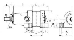
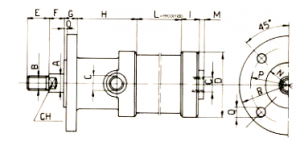
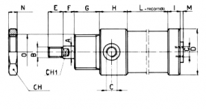
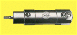
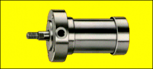
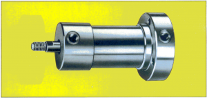
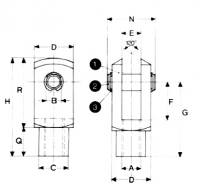
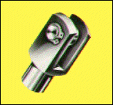
This device has got three parts rod clevis:
(1) The rod clevis, Built in Steel
(2) bolt built in burnished Steel
(3) Two elastic rings built in special steel

Tipo A B B Tolerancias acoplamiento C D E E Tolerancias acoplamiento F G H N Q R
FPF6 M 6 x 1 6 H-11 10 12 6 H-13 12 24 31 18 12 19
FPF8 M 8 x 1,25 8 H-11 14 16 8 H-13 16 32 42 22 12 30
FPF10 M 10 x 1,5 10 H-11 18 20 10 H-13 20 40 52 27 15 37
FPF12 M 12 x 1,75 12 H-11 20 24 12 H-13 24 48 62 31 18 44
FPF14 M 14 x 2 14 H-11 24 27 14 H-13 27 56 72 34 23 49
FPF16 M 16 x 2 16 H-11 26 32 16 H-13 32 64 83 39 24 59
FPF18 M 18 x 2,5 16 H-11 26 32 16 H-13 32 64 83 39 24 59
FPF20 M 20 x 2,5 16 H-11 35 45 23 H-13 25 65 80 54 31 49
FPF24 M 24 x 3 20 H-11 50 60 30 H-13 30 85 105 69 42 63
FPF27 M 27 x 3 20 H-11 50 60 30 H-13 30 85 105 69 42 63
FPF33 M 33 x 3,5 30 H-11 55 70 30 H-13 35 87 120 80 40 80