|
|
U-32/R |
U-40/R |
U-50/R |
U-63/R |
U-80/R |
U-100/R |
U-125/R |
U-160/R |
U-200/R |
U-250/R |
U-300/R |
|
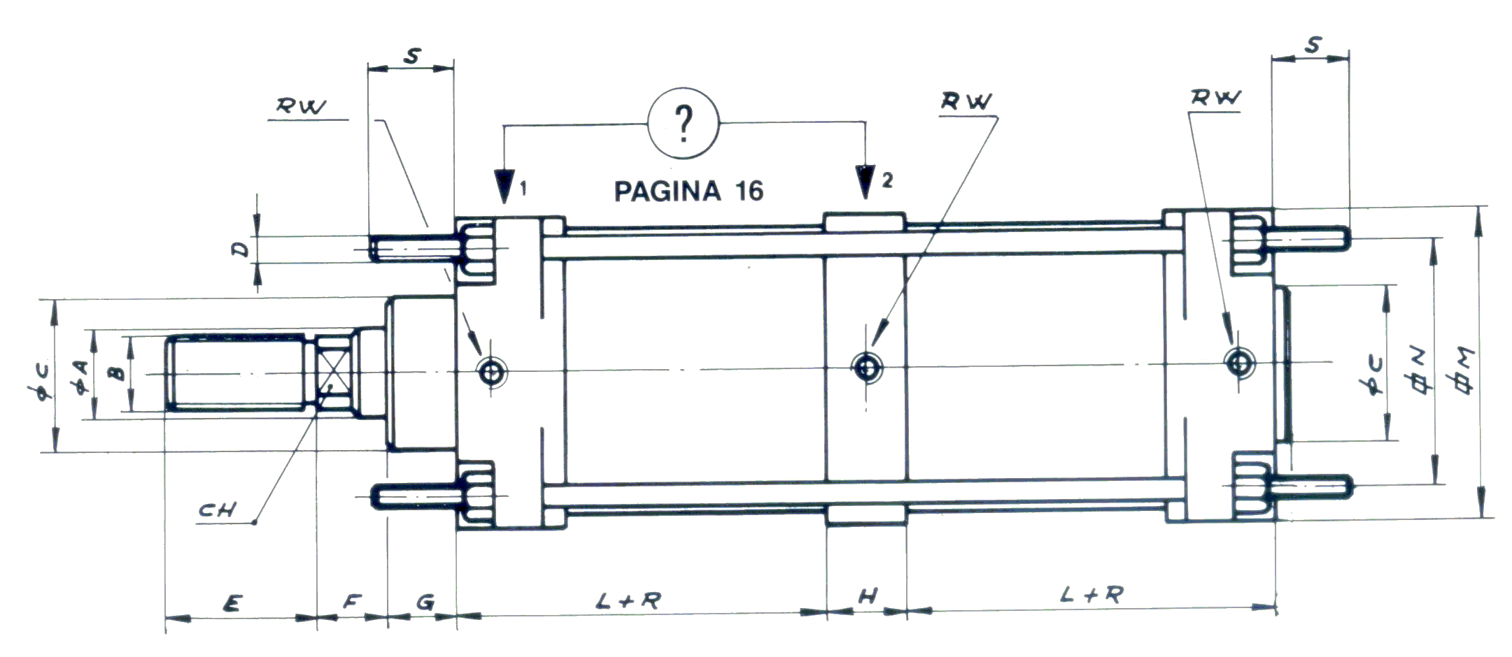
A |
12 |
18 |
18 |
22 |
22 |
30 |
30 |
40 |
40 |
60 |
60 |
|
B |
M-10×1,5 |
M-16×1,5 |
M-16×1,5 |
M-20×1,5 |
M-20×1,5 |
M-27×2 |
M-27×2 |
M-36×2 |
M-36×2 |
M-50×3 |
M-50×3 |
|
C |
25 |
32 |
32 |
45 |
45 |
55 |
55 |
65 |
65 |
102 |
102 |
|
CH |
8 |
13 |
13 |
17 |
17 |
22 |
22 |
32 |
32 |
47 |
47 |
|
D |
M-6 |
M-6 |
M-8 |
M-8 |
M-10 |
M-10 |
M-12 |
M-16 |
M-16 |
M-20 |
M-24 |
|
E |
20 |
36 |
36 |
46 |
46 |
63 |
63 |
85 |
85 |
70 |
70 |
|
F |
10 |
19 |
19 |
19 |
19 |
27 |
27 |
25 |
25 |
30 |
30 |
|
G |
15 |
15 |
15 |
20 |
20 |
20 |
20 |
25 |
25 |
48 |
48 |
|
H |
15 |
15 |
15 |
35 |
35 |
40 |
40 |
50 |
50 |
60 |
60 |
|
L + R |
37 + R |
45 + R |
45 + R |
44 + R |
44 + R |
54 + R |
54 + R |
42 + R |
42 + R |
72 + R |
72 + R |
|
M |
45 |
52 |
65 |
75 |
95 |
115 |
140 |
180 |
220 |
270 |
320 |
|
N |
33 |
40 |
49 |
59 |
75 |
90 |
110 |
140 |
175 |
208 |
260 |
|
S |
33 |
40 |
49 |
59 |
75 |
90 |
110 |
140 |
175 |
208 |
260 |
|
Rw |
1/8’’ G |
1/4’’ G |
1/4’’ G |
3/8’’ G |
3/8’’ G |
3/8’’ G |
1/2’’ G |
1/2’’ G |
3/4’’ G |
3/4’’ G |
1’’ G |