|
32 Ø |
40 Ø |
50 Ø |
63 Ø |
80 Ø |
100 Ø |
125 Ø |
160 Ø |
200 Ø |
250 Ø |
300 Ø |
|
| A |
12 |
18 |
22 |
30 |
40 |
60 |
|||||
| B CNOMO |
M-10X15 |
M-16X1,5 |
M-20X1,5 |
M-27X2 |
M-36X2 |
M-50X3 |
|||||
| B CETOP |
M-10X1,5 |
M-12X1,25 |
M-16X1,5 |
M-20X1,5 |
M-24X2 |
M-36X2 |
M-50X3 |
||||
| B ISO |
M-10X1,5 |
M-12X1,25 |
M-16X1,5 |
M-20X1,5 |
M-27X2 |
M-36X2 |
M-50X3 |
||||
| C |
25 |
32 |
45 |
55 |
65 |
102 |
|||||
| CH |
8 |
13 |
17 |
22 |
32 |
47 |
|||||
| D |
M-6 |
M-8 |
M-10 |
M-12 |
M-16 |
M-20 |
M-24 |
||||
| E CNOMO |
20 |
36 |
45 |
63 |
85 |
70 |
|||||
| E CETOP |
20 |
24 |
32 |
40 |
48 |
72 |
70 |
||||
| E ISO |
22 |
24 |
32 |
40 |
54 |
72 |
70 |
||||
| F CNOMO |
10 |
19 |
19 |
27 |
25 |
30 |
|||||
| F CETOP ISO |
9 |
13 |
20 |
15 |
22 |
27 |
41 |
55 |
65 |
30 |
|
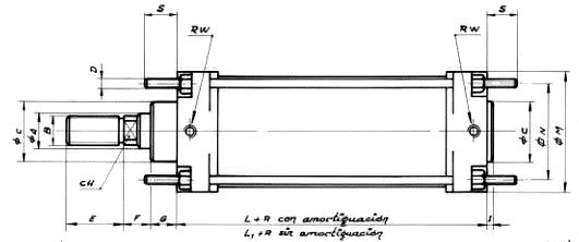
| G |
15 |
20 |
25 |
48 |
|||||||
| RW |
1/8 |
1/4 |
3/8 |
1/2 |
1/2 |
3/4 |
|||||
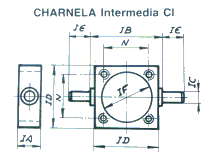
| M |
45 |
52 |
65 |
75 |
95 |
115 |
140 |
180 |
220 |
270 |
320 |
| N |
33 |
40 |
49 |
59 |
75 |
90 |
110 |
140 |
175 |
208 |
260 |
| L + R CNOMO |
80 |
110 |
125 |
145 |
180 |
231 |
|||||
| L + R CETOP ISO |
98 |
110 |
125 |
136 |
145 |
168 |
180 |
190 |
231 |
||
| L1 + R |
64 + R |
78 + R |
76 + R |
93 + R |
102 + R |
152 |
|||||
| S |
17 |
23 |
28 |
34 |
43 |
70 |
|||||